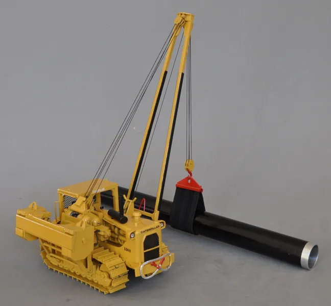
Custom scale model builder Ad Gevers has again finished a unique project: Building a Caterpillar 594H Pipelayer by using as donor model the Conrad Caterpillar 594 Pipelayer in 1:50th scale.
It is our goal in this "making of ...." to show how this custom model is been achieved. Ad Gevers, shares his building skills through the photos with little notes guiding us in the construction process. Gradually it shows the making of a unique model of the Caterpillar 594H Pipelayer.
Enjoy reading & watching!
Ad and Wouter
The undercarriage
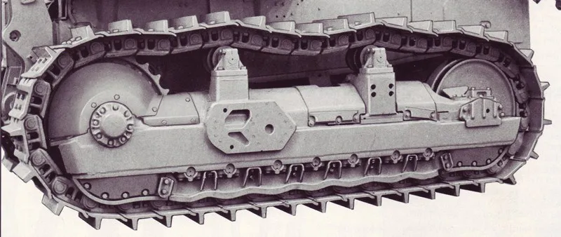
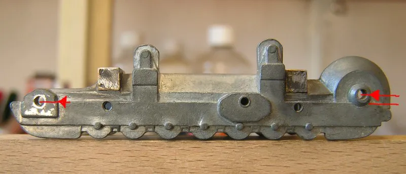
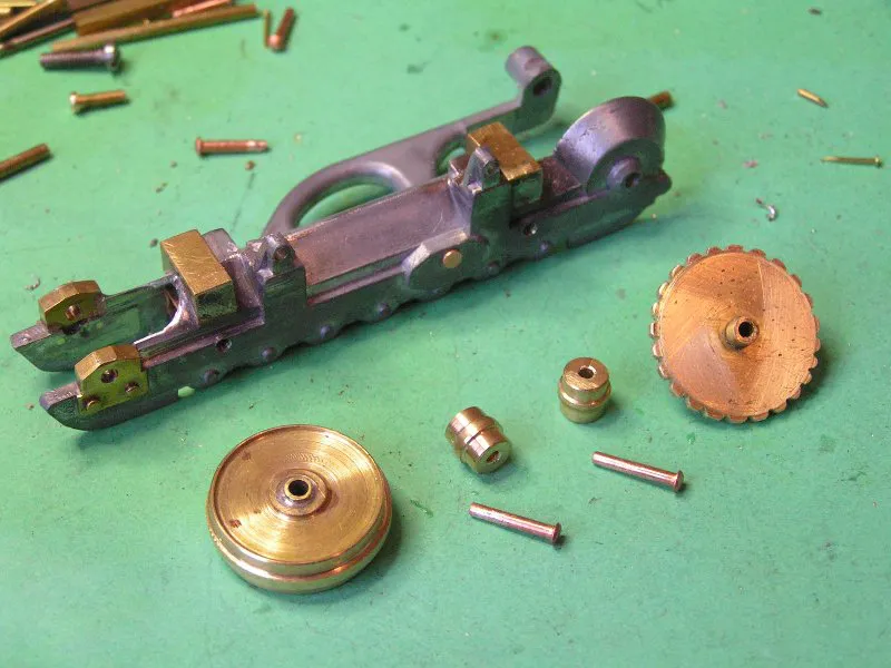
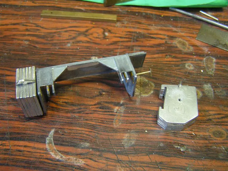
The system with the rubber tracks of the Conrad model is so bad that I have to do something about it. To put metal tracks on it I must first adjust the tensioning wheel and the sprocket on the same horizontal level.The center of the tensioning wheel should be placed higher. The 1:1 machine has eight idlers. The donor model has only seven. This would mean creating a whole new undercarriage should be made but this is to much effort so far and I have chosen to maintain this situation.
The shoes
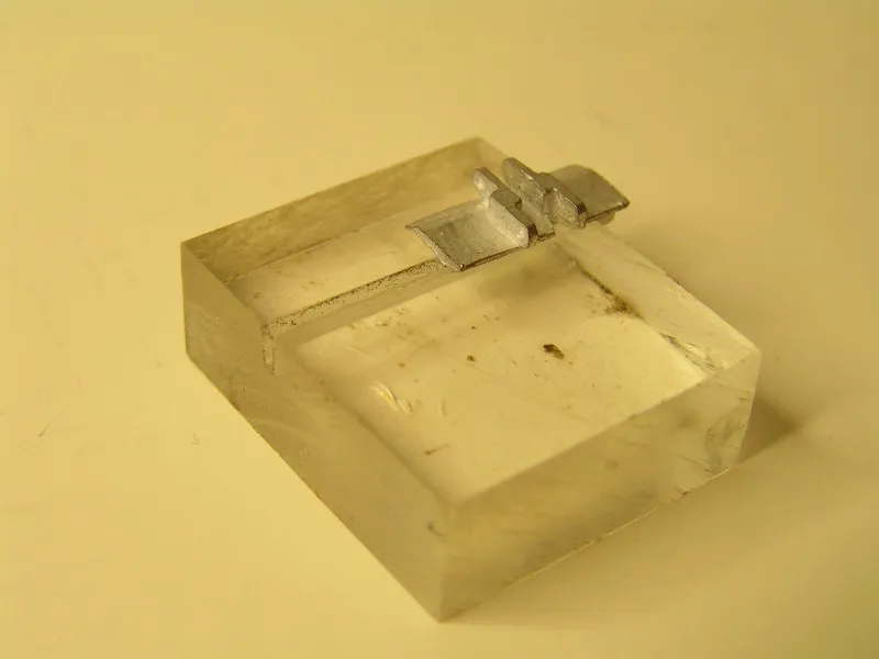
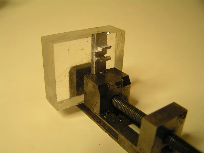
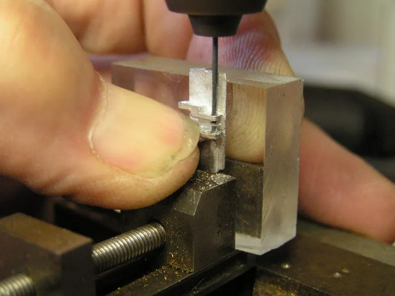
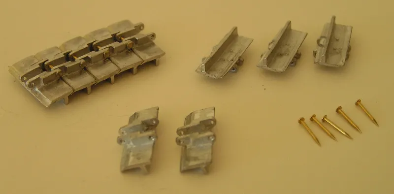
Fortunately at the Modelshow Europe in Ede I was able to buy beautiful cast track shoes sized 15.2 mm. This means recalculated to 1:1th scale shoes of 76 cm which is very near the 86 cm shoes which are on the 1:1 Pipelayer mounted. It is customary that the shoes are on Pipelayer wider than the standard Track-Type Tractor. First I made in a plexiglass cube a slot. Now I get the Shoe fixed so I could drill vertical holes of 0.6 mm. This drilling I have done alternating to avoid the chance that I would inclined drilling. Then the links are soldered together with 0.5 mm nails.
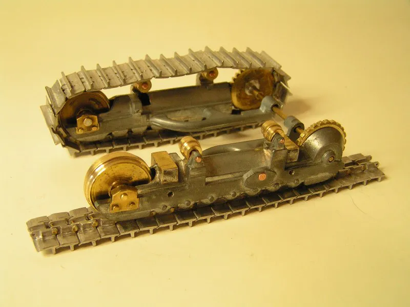
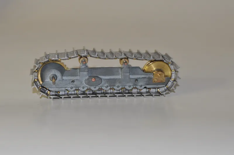
The undercarriage and shoes put together
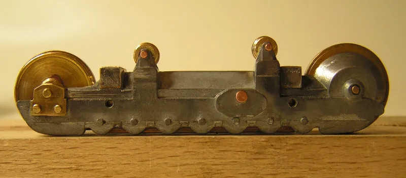
Using the following detailed photos you can see in detail how the undercarriage is further adapted and finally composed.
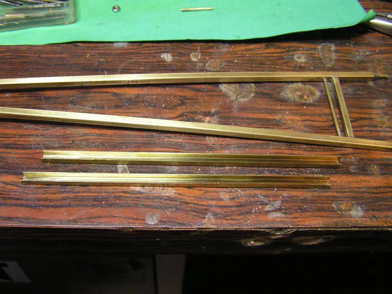
To create a proper guiding of the metal shoes the design also has a hidden brass beam in the undercarriage so the completed shoes run smoothly and tighter around the chassis when they rotate.
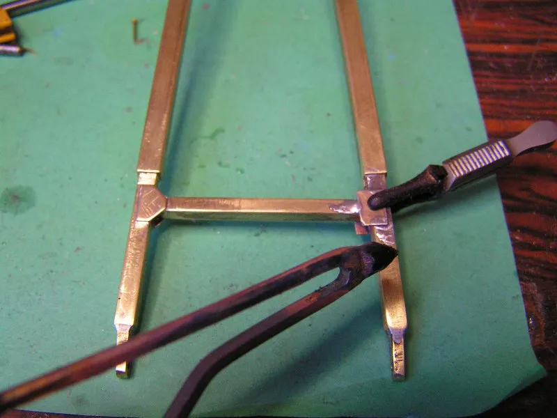
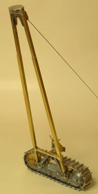
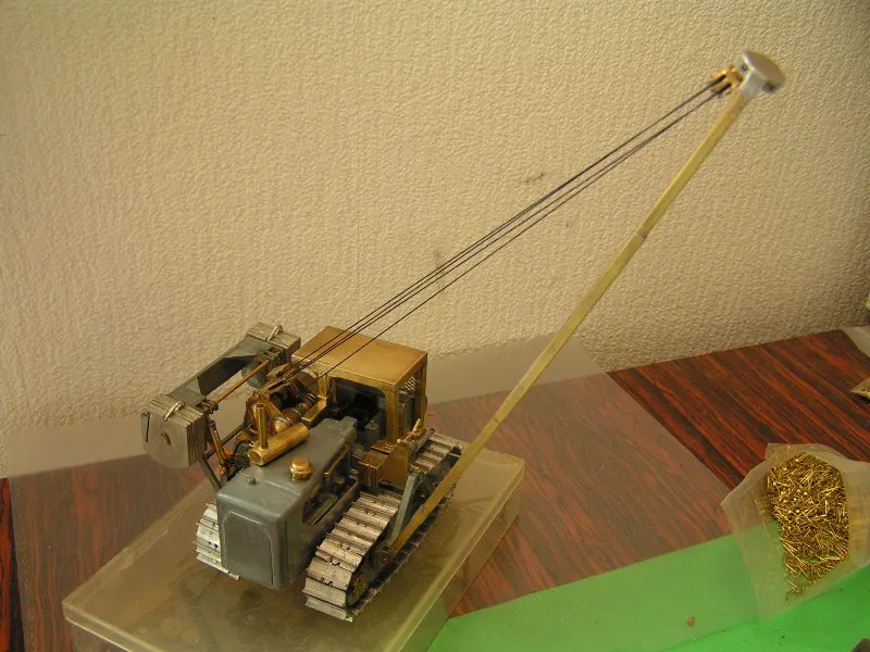
The Boom
The boom is composed of the elements of the master boom of the previously released cADSttachements KIT #25 and finished with extra reinforcements and some attention to small details. This means I have chosen for an extra-long boom to place on this Caterpillar 594H Pipelayer. There are two U profiles at the lower end of the boom soldered. Later on they will be painted black so they look like rubber that serves to protect the boom against the damage to hoist loads.
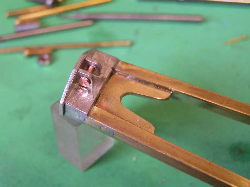
To clarify some of the applied details I have add an extra photo of the additional reinforcements of the framework from the boom.
Next step was to create a completly handmade boom stop and cable guide made ?brass and metal parts.
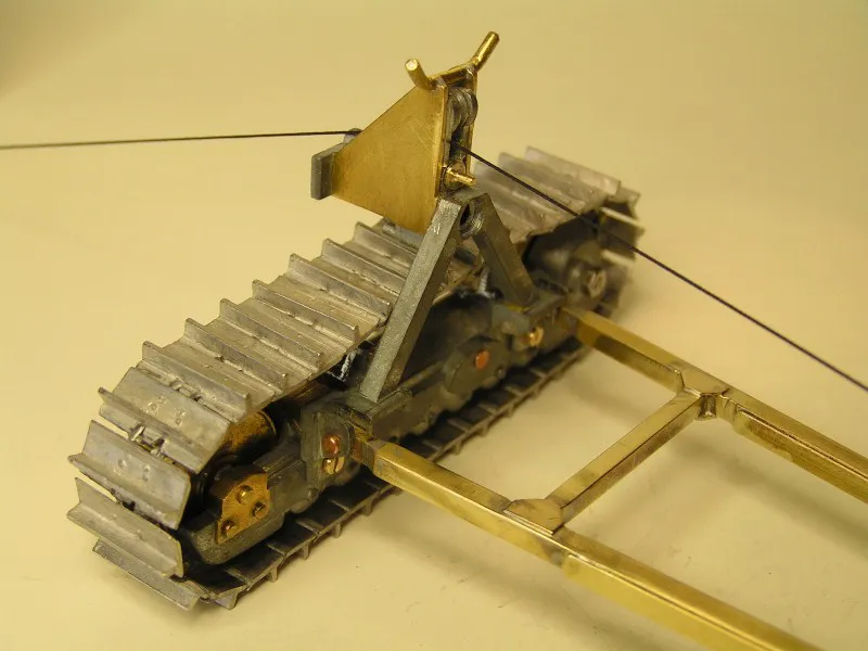
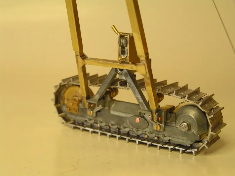
The Boom assembly to the Undercarriage
I bolted the frame of the Boom to the Undercarriage the same way as the real thing is done. The frame is stripped of all right angles by the mounting points of the boom.
Have found that despite everything is calculated and pre-trial mounted, the bottom frame of the boom now just touches. So it is necessary to put a few mm filling between them so the tracks are running completely free on the undercarriage and do not hit the frame from the boom.
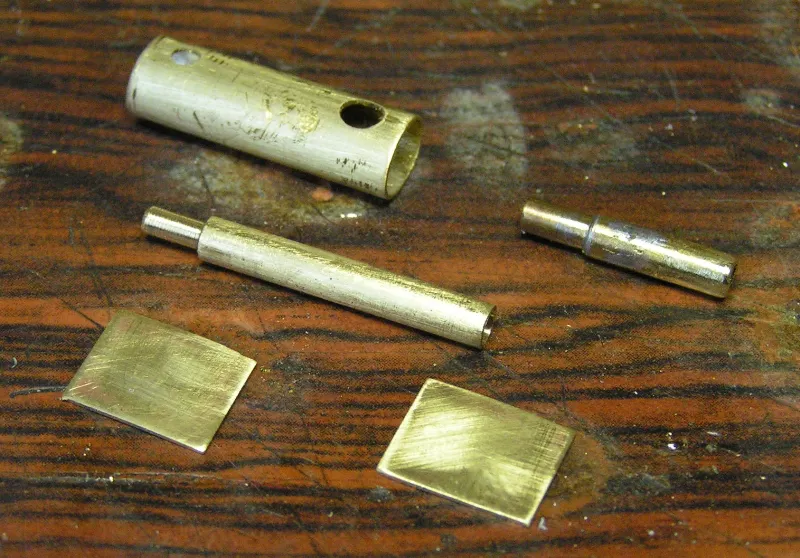
The Fueltank
The content of the fuel tank of a Caterpillar 594 (757 liters) and Caterpillar 594H (760 liters) differed not so much, but the place where Conrad has placed on the model is incorrect. Conrad model is based on the Caterpillar Track-Type Tractor D9G where the fueltank position is not in the middle. Conrad only removed the Hydro tank and did nothing else.
I was set on to put the fuel tank in the center of the machine. After the tank is finished and painted the right color unfortunately almost nothing will be seen from a week of work and patience.
It took some arithmetic to decide how much material to shorten on one side and how much material to add on the other side. This is because the tank and floor plate is molded in one piece.
Because the cut is always slightly deviating I had to add a brass plate of 0.5 mm for the proper sizing. Coincidentally, I was able to glue the outside easier and it improved the return attaching.
On the right comes a brass plate of 3mm. This brass plate is also slightly larger than the tank and when the glue has hardened it is hand filed into the correct size and shape.
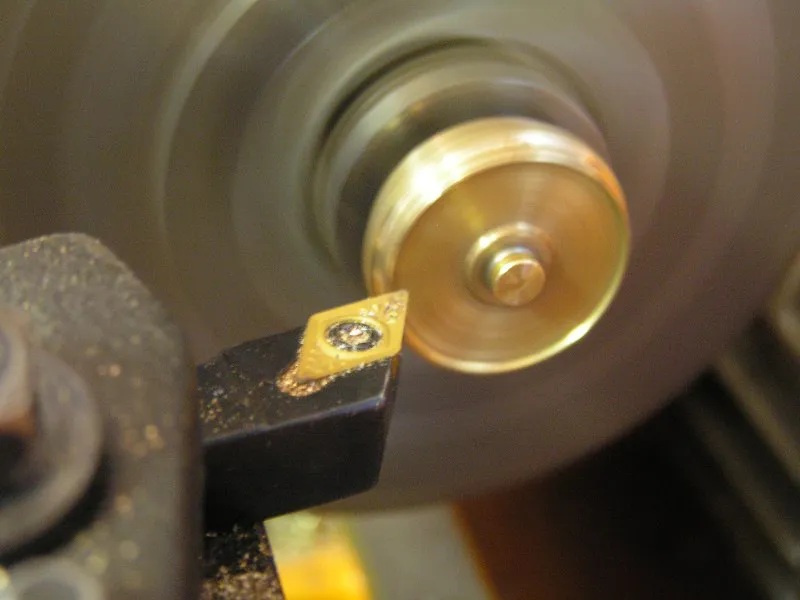
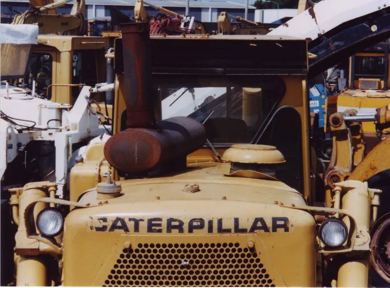
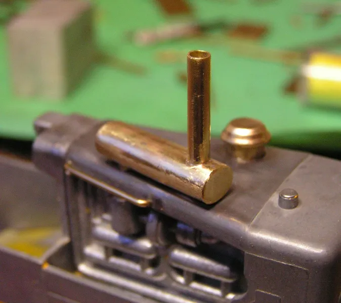
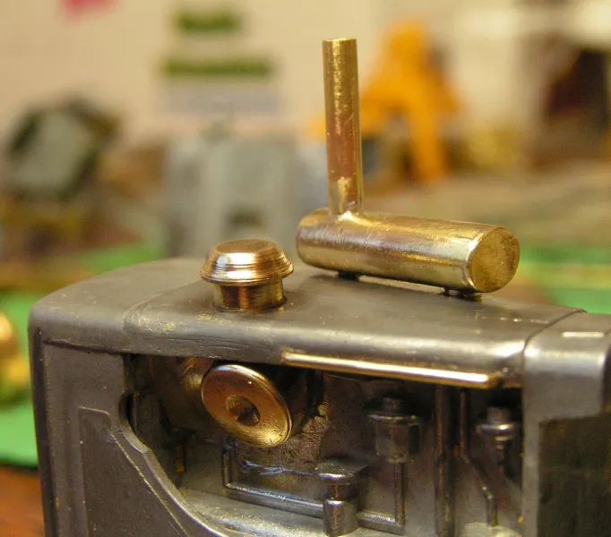
The Finall result: the Fuel tank exactly in the center and also added a new brass made fuel filler cap on top!
By comparison, the picture of the fuel tank of the machine 1:1.
The rear Winch
For starters I decided to make use of the winch kit from EMD to build the rear Winch for my Caterpillar 594H.This Kit is still available through Buffalo Road Imports and is from the EMD E-series. The kit is made from white metal parts and has #EMDE104K.
Order? Click here: D9G winch kit metal rotating drum
This kit comes closest to the winch Caterpillar Cat 58-59.Using this available kit parts makes building my custom pipelayer winch much easier. I just made ??a few small adjustments so the winch fits better on the back of the model. Of course I added for more detail a real piece of steel cable on the rotatingdrum.
The Exhaust
Today it's time for a small project:The thick exhaust modeled on the last type of D9H Caterpillar machine.The pictures speak for themselves, a mini-masterpiece is the end result.
The Finall Drive
The following photos actually should had been placed in front off the construction of the Fueltank and the Winch. But because they turned up later I inserted them not earlier.
I had to make an adjustment to the base frame. Because the rear axle is inserted in the middle the final drive position is now too low. This is why I have removed the final drive and hand made two new brass ones and then glued those to the base frame. For gluing brass material on to diecast material I use a two-component adhesive.
It is much work you later hardly see, but yes the end result should be as closely as possible the real Caterpillar 954H Pipelayer appear.
The bottom plate
To remove the existing paint from a scale model I use a paint remover. I dip the part into the tin and subsequently put it in a bag. Now I can rub over it without getting dirty hands and achieve that almost all paint gets loose.
If you then take the part out of the bag there remains already much paint behind that, when rinsing with water, does not get in the sewer system. Therefore this method is also much better for the environment.
A Pipelayer is a rigid machine and therefore I had to replace the movable equalizer spring, which it originates Caterpillar D9 Crawler dozer is fitted, by a homemade fixed equalizer spring of brass material.
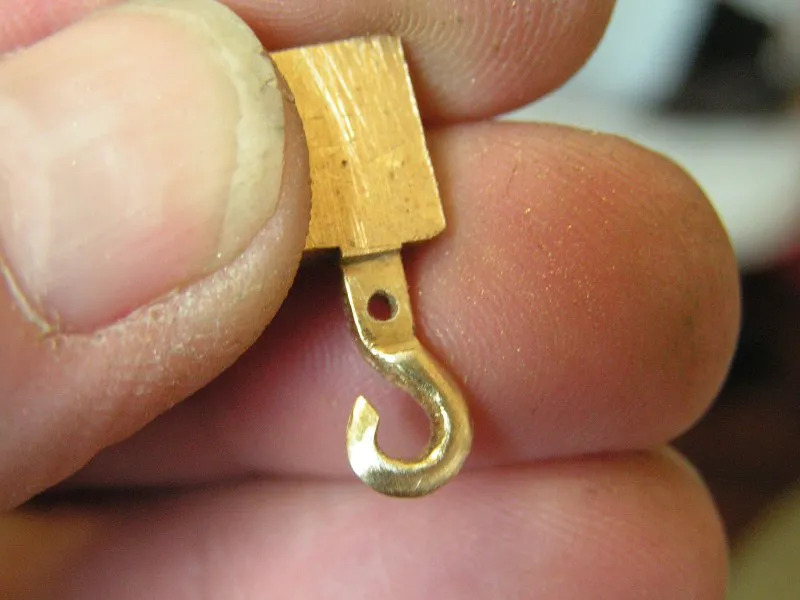
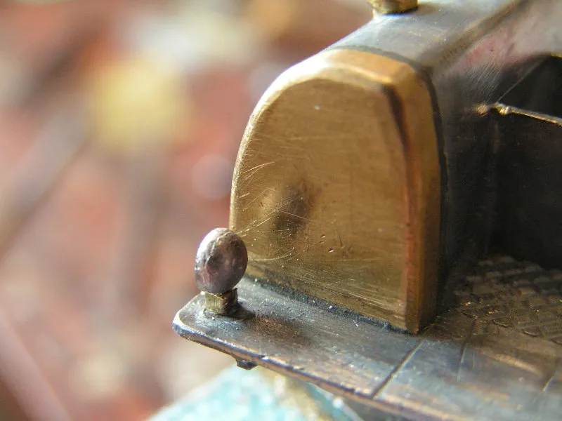
To finish the bottom plate I mounted a homemade pull hook of brass material on the front side.
The winch
Whether or not installing a new hydro winch on this Caterpillar 594H Pipelayer meant the necessary reflections.
Finally I made the decision and the choice fell on placing the winch work of the Superior CPX Conversion kit. Although it was difficult to find data, I still managed to hit upon some photos on the Internet.
This meant that I needed to improvise a lot, especially because a spring had to be built in to prevent that the boom not lowers because of the weight of its load. Consequence is unfortunately causing dimensions on the scale model deviates from the original dimensions
The Counterweight
For all individual counterweight plates to place I had create some more room on the existing frame. The counterweight plates used come from our own cADSttachements series.
This kit is still available at Buffalo Road Imports The kit is made of white metal parts with number #AGM25. Order? Click here: "Manufacturer" and then select "Ad Gevers Models".
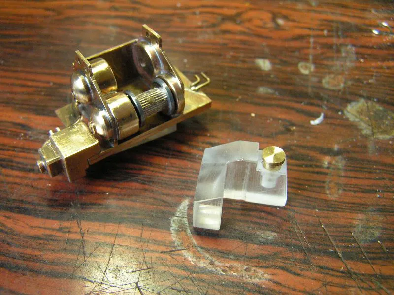
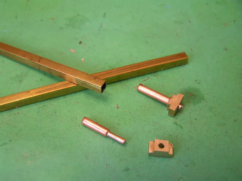
When I large pieces of solid body parts have to make I usually use perspex as base material, as at present for the Hydro tank of this Caterpillar 594H Pipelayer.
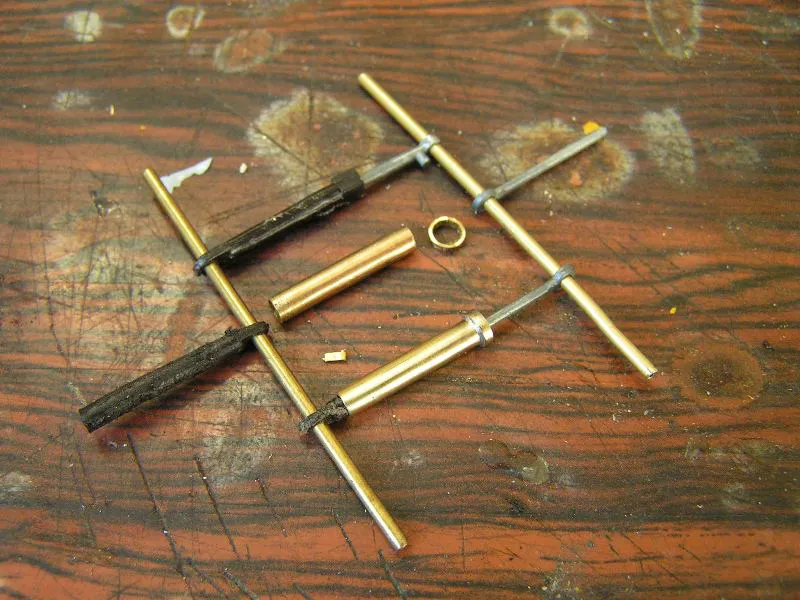
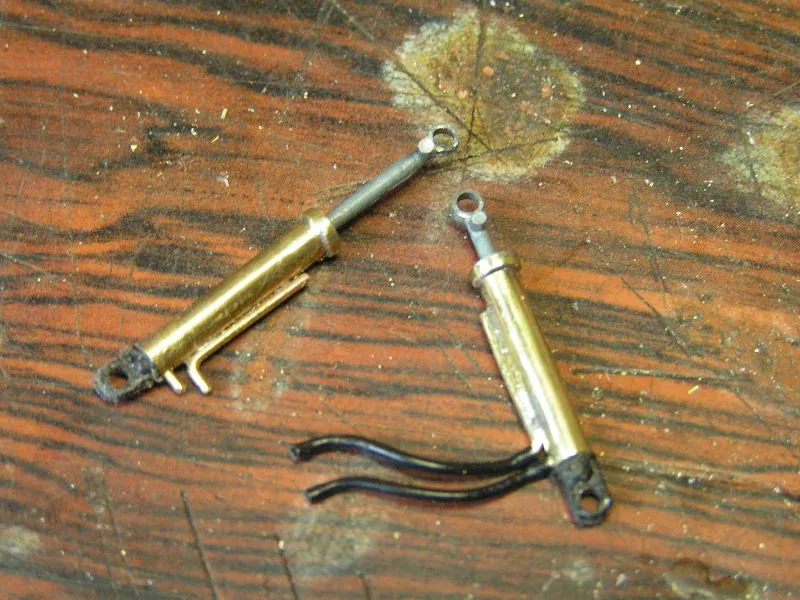
The present plastic cylinders of the donor scale model are always hard on spraying and so instead I like to put a brass tube over it. This way I can also facilitate the connections for the Hydro hoses places more easier. The end result is immediately looking far more realistic.
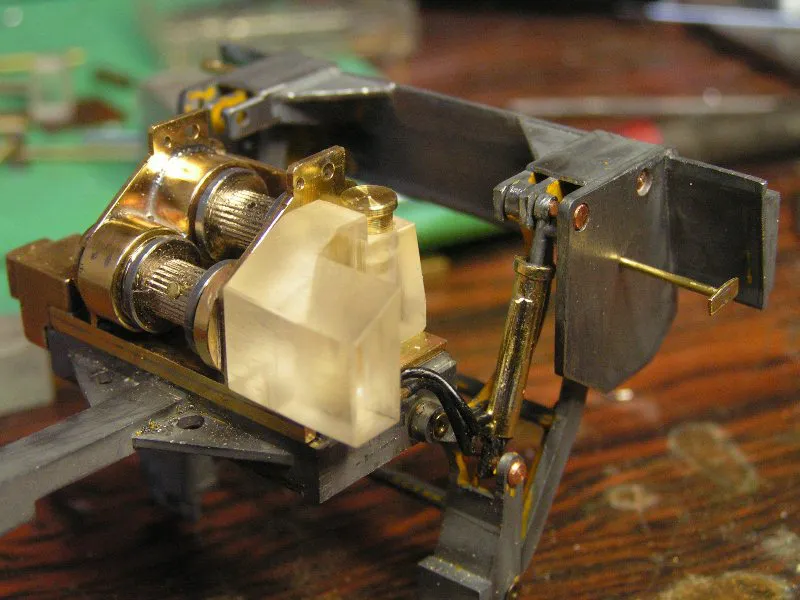
Finally, the placement of the modified Hydro tank and lift cylinders on the frame of the counterweight together with the winch driving gear.
The ROPS
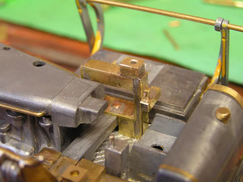
A modernized Caterpillar 594H Pipelayer can not without a new and mandatory ROPS.In this case a completely customized mini masterpiece of brass.
In order to provide a firm connection I make use of rivets at the corners. This is necessary because of the heat released in the roof when soldering. Without using the rivets, the whole construction will be warping or fall apart.
Detail of the left support center with the new battery box.
Detail of the right support center, which required some really special job skills to put it together and construct the point of attachment in place, but the end result seems quite adequate to the real implementation.
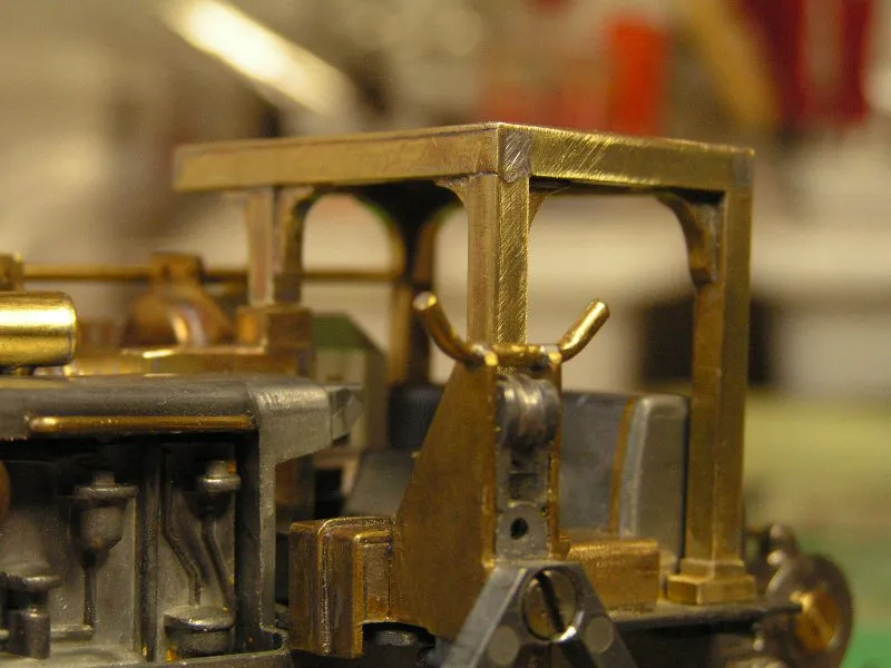
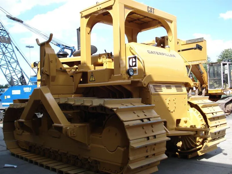
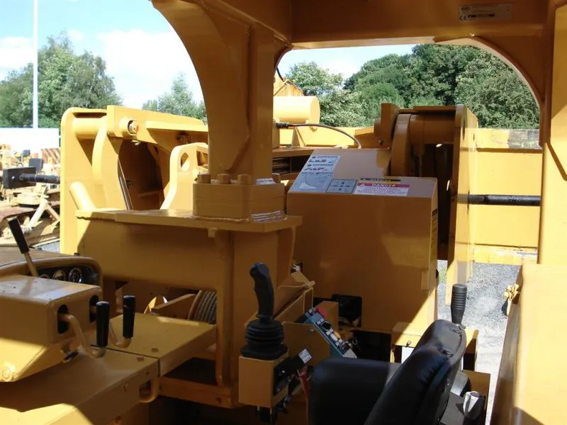
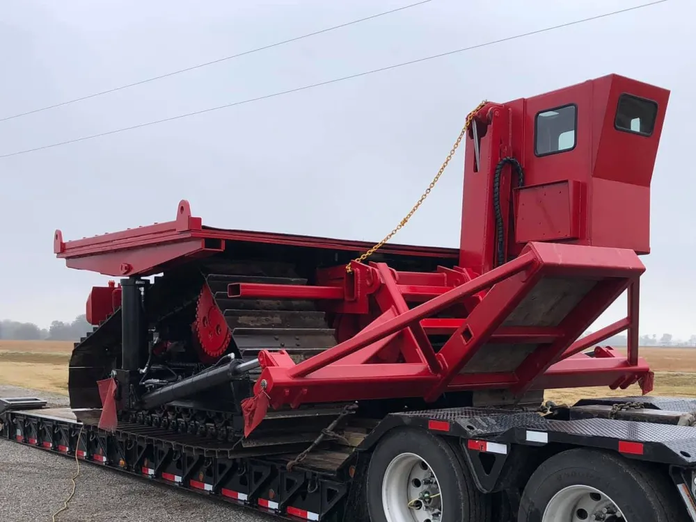
On the last series of photos the end result of this customization open ROPS placed on our Caterpillar 594H Pipelayer and to compare I have added some photos of the machine in 1:1.
The safety grille
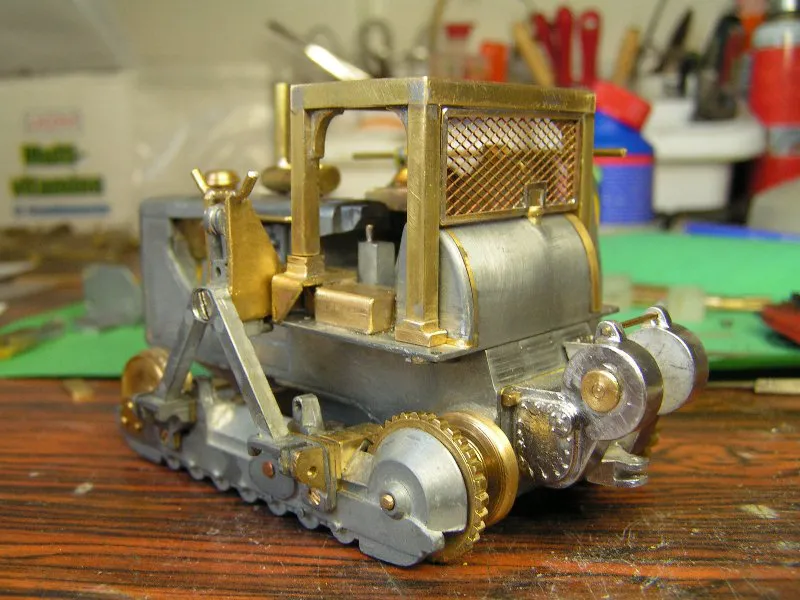
These Caterpillar 594H Pipelayer is equipped with a winch behind the machine.
To reduce the risk of a cable breaking down and to prevent our operator will be hit the open ROPS is provided with an additional safety grille in the rear side of the ROPS. Safety first!!!
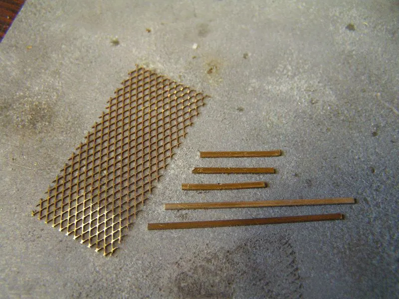
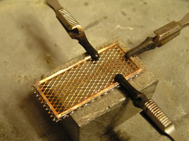
The grille is made of brass and brass wire mesh profiles. This is done by soldering al the parts to each other.
The brass mesh is cut too large and soldered to the outer edge. Then simply remove the excess material and you have a very tight constructed grille.
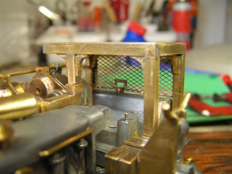
At the place where the grille and the fuel filler cap conflict is with a little modification in the frame made the required cutout and the end result shows that the safety grille can be installed without problems
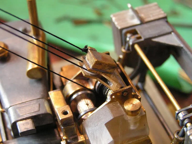
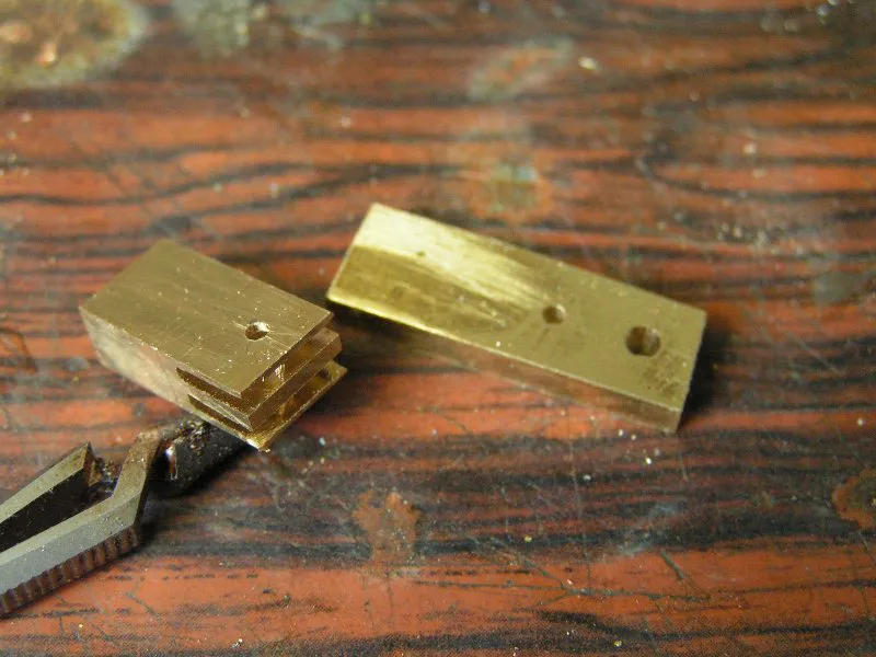
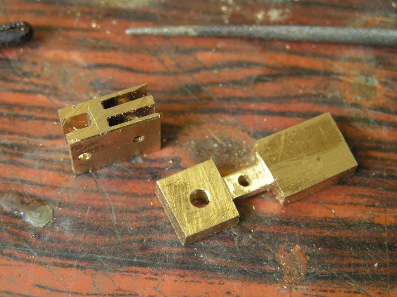
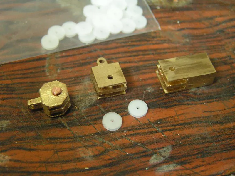
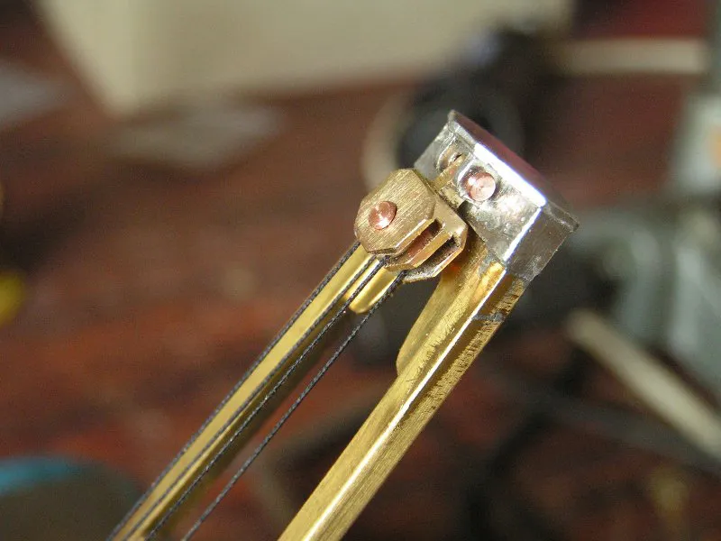
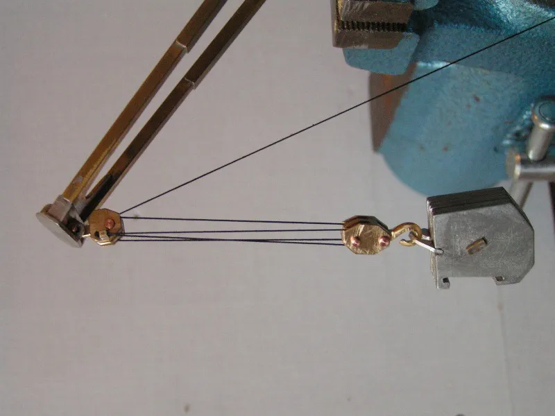
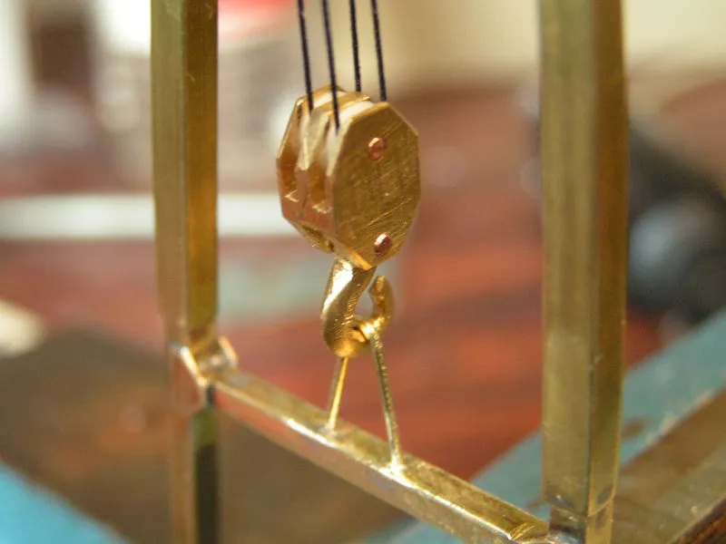
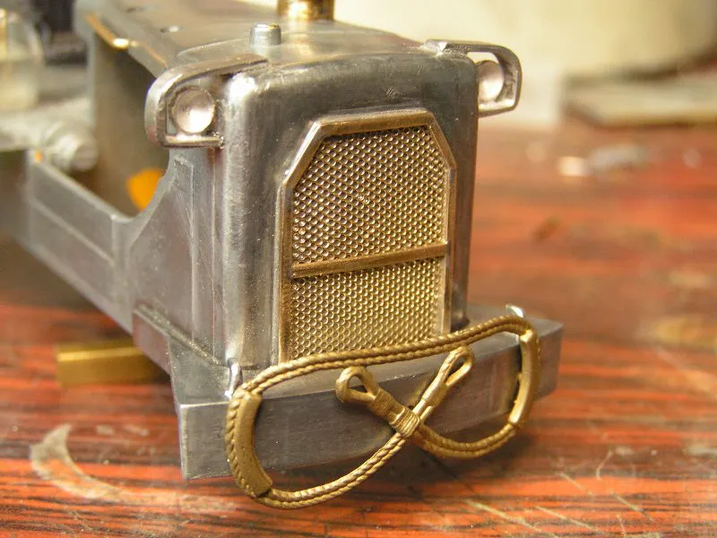
The pulley blocks and hoist hook
To lower and raise the boom and the load I constructed the required pulley blocks and hoist hook from brass material.
The details
Here are the latest series of photos of the construction of the Caterpillar 594H Pipelayer. The applied details give this model really a finishing touch!
Hand grips and hooks to place the ROPS on the machine.
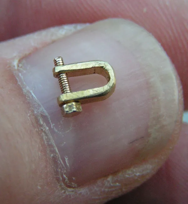
The construction of a shackle!!!!
The possibility for the securing of the hook block while driving without load.
The necessary work lights on the back of the machine.
The control, switching, security, and winch control levers and also another chair placed for the operator.
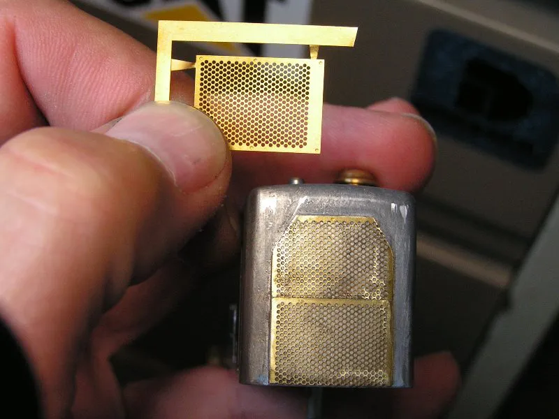
Ad Gevers did want to have a real looking grill and not just an added sticker. Therefore he used this photo etching plates with the proper hole pattern. The grill belongs actually to lie within the engine cover, but at this stage of the building did he not want to make that change.
The headlights and a strong pull cable and also the hooks on the front bumper are filed in the correct form.
The final steps
After the first base coat there always reveal some bumps which need to be filled with Filler. So after a final sanding and polishing turn and a final check that all parts fit the model all parts are completely ready for carefully degrease and applying the final coat in the Caterpillar color.
The parts are degreased and pre-heated for a better adhesion of the paint and then sprayed directly in a dust-free room.
Now comes the most difficult moment: You would like to merge all parts and admire the end result but you should wait at least 2 weeks after spraying before the model can be put together. Then only is the paint hardened sufficiently.
YES! The final result: The Caterpillar 594H Pipelayer.To view all the photos and admire this unique model? Look in the category Pipelayers or click on the photo here below.