Custom schaalmodel bouwer Thomas Wilk heeft een uniek project afgerond en bouwde speciaal voor de Modelshow Europe 2016:
- Caterpillar D6K Lastractor
In deze Making-of Caterpillar D6K Lastractor oftewel "kijkje achter de schermen" zullen wij u laten zien hoe dit custom model tot stand is gekomen.
Thomas Wilk leidt ons middels zijn bouwimpressie foto's met kleine toelichtingen door zijn bouwproces zodat u op basis van het schaalmodel van de Caterpillar D6K Rupsdozer van Norscot in schaal 1:50 stap voor stap een uniek schaalmodel van de Caterpillar D6K Lastractor ziet ontstaan en voegde er ( zoals gebruikelijk -)) weer een groot aantal extra details aan toe. Maar zoals je zult zien was het model hiermee nog niet compleet genoeg. Hij ontwierp en maakte een bijpassend diorama zodat er met recht een klein museumstuk tot stand kwam.
Veel kijk en leesplezier!
Thomas en Wouter
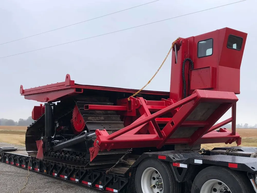
De Lastractor
De Lastractor is eigenlijk een mini fabriek op rupsen binnen de pijpleiding industrie. De machine levert de lassers alles wat ze nodig hebben op een pijpleiding project in het veld: gelijkstroom D.C of wisselstroom A.C., Las vermogen en de luchtdruk zodat ze op elke locatie en als het moet in niemands land hun werk te kunnen verrichten.
In het verleden was de eigen motor van de lastractor de belangrijkste energiebron om de energie voor het lassen te leveren. Dus draaide de motor gedurende de gehele dag bij hoge toeren zonder dat de machine vaak ook maar enige afstand in het veld hoefde te rijden.
Vandaag de dag is het veelal gebruikelijk om extra generator sets te gebruiken om de klus te klaren. Vaak worden ze gemonteerd aan de achterkant van de machine als een logische tegenwicht van de aan de voorzijde gemonteerde hydraulisch laadkraan. De hydraulisch laadkraan dient voor het verplaatsen van de gas- en propaan flessen en voor het in de juiste positie houden van de las tent, zodat de lassers afgeschermd van de weersinvloeden de vereiste kwaliteit las verbindingen op de pijplijn kunnen aanbrengen.
Elke machine wordt min of meer op maat gemaakt op verzoek van de klant en is qua uitvoering en uitrusting sterk afhankelijk van bijvoorbeeld voor welke lasproces hij gebruikt gaat worden. Gebruikt men het lasdraad proces dan volstaan alleen wat propaan flessen voor het verhitten van de lasnaad. Steeds vaker maakt men echter gebruik van (geautomatiseerde) hoogwaardige lastechnieken en dan is het dus van cruciaal belang dat alle mogelijke voorzorgmaatregelen worden genomen en zal men dus algauw overgaan tot het gebruik van een grote las tent: slechts een klein beetje tocht van buitenaf kan de kwaliteit van de lasnaad vernietigen. De meeste verbindingen bestaan uit verschillende lagen lasnaden. Een slechte las kan uiteindelijk leiden tot lekkage van de pijpleiding met alle mogelijke gevolgen van dien.
De start: "Made in Zwitserland"
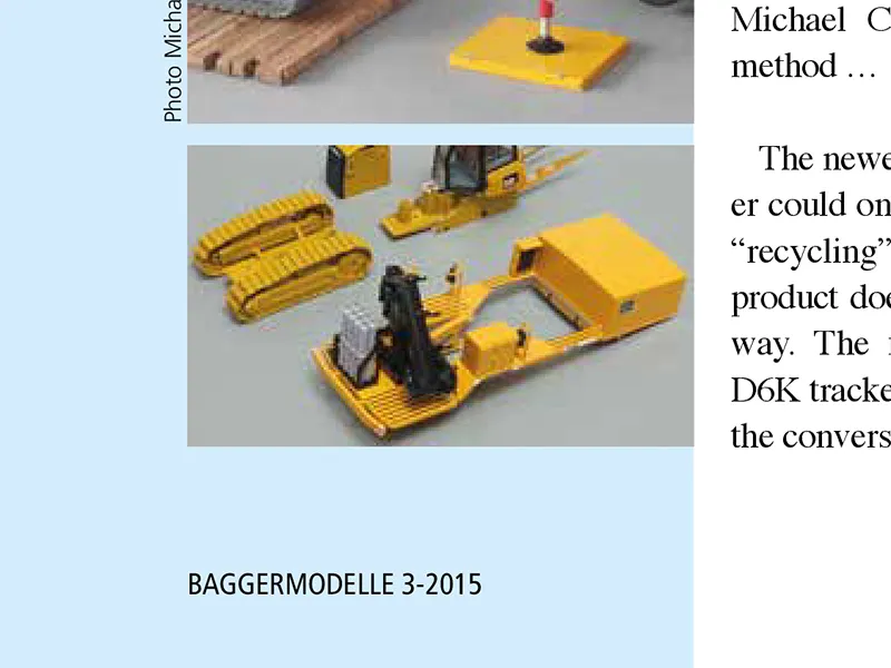
Met toestemming van Daniel Wietlisbach (bedankt!) mag ik hier het originele artikel van Urs Peyer dat gepubliceerd werd in BAGGERMODELLE 3-2015 op mijn website met u delen. DE kans voor iedereen die het nummer heeft gemist om alsnog zelf dit unieke model te nabouwen.
BAGGERMODELLE is HET colour magazine voor verzamelaars van bouw-machine-modellen, kranen en zwaar transport. Het blad is Duitstalig. Gedetailleerde Engels vertalingen van de belangrijkste inhoud en artikelen zijn beschikbaar op de website en via de App.
Een MUST HAVE voor iedere verzamelaar en fan van (custom) bouwmachine schaalmodellen.
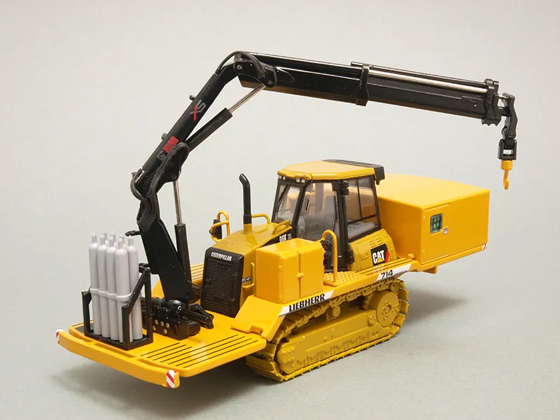
Op basis van het schaalmodel van de Caterpillar D6K XL Rupsdozer van Norscot in schaal 1:50 realiseerde custom bouwer en vriend Urs Peyer voor Thomas de Caterpillar D6K Lastractor.
We delen met hoe Urs Peyer te werk ging en de omzetting en de benodigde aanpassingen naar de Caterpillar D6K Lastractor heeft gerealiseerd die vervolgens weer diende als startpunt van Thomas.
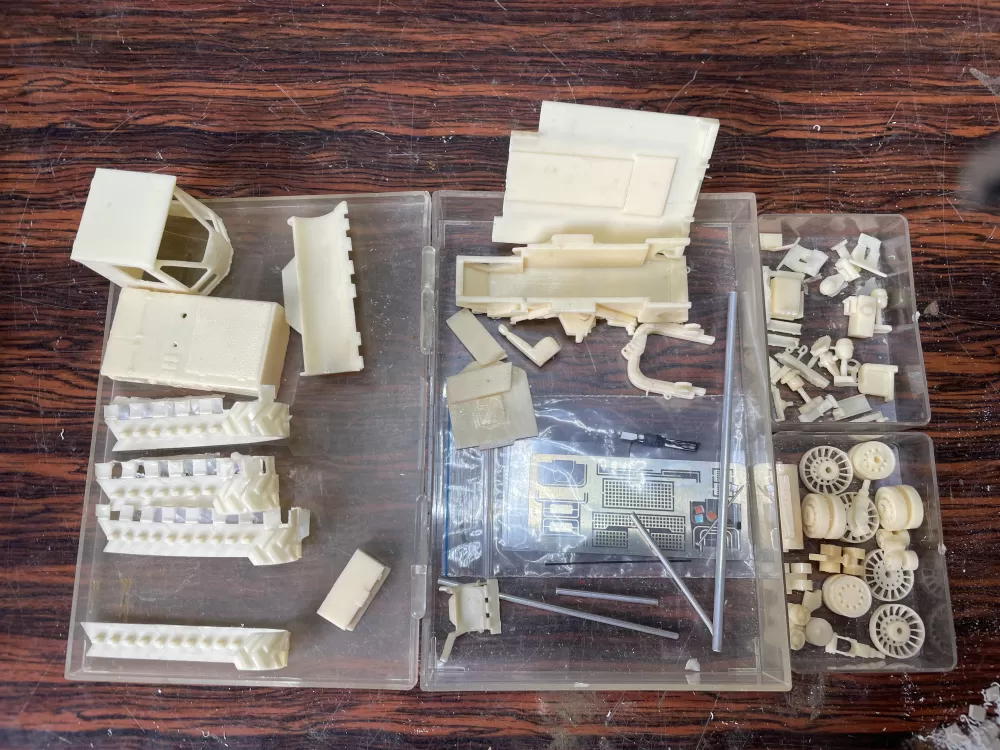
Door Caterpillar is tot op heden nog geen schaalmodel van een Lastractor uitgebracht. Om dit gat op te vullen maakte Urs dus dankbaar gebruik van de Liebherr SR 714 “Schweißraupe” oftewel Lastractor in schaal 1:50 die door NZG onder artikelnummer #855 is uitgebracht. Van het Liebherr donor schaalmodel wordt de achterste structuur met de lasgeneratoren en lasapparatuur omgezet en van de voorzijde worden de Hiab kraan, de gasflessenbatterijen en de twee looppaden links en rechts van de trekker gebruikt.
Aan de slag!
De demontage
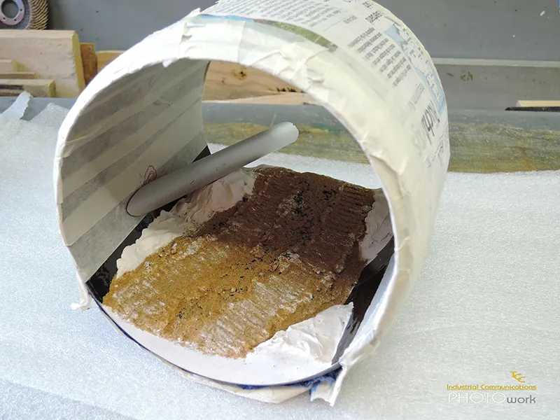
The Caterpillar dozer can be broken down into four parts quite easily by the removal of four screws. The blade with pushing frame and hydraulic cylinder is attached to the frame with four bolts. These can be pulled out very carefully with a side cutter. The four bolts on the ripping attachment have to be drilled and pulled out.
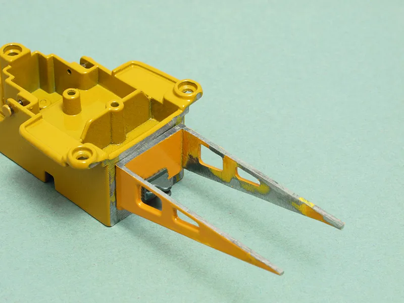
Next, the four support brackets for it are sawn off flush with the frame and filed smooth as shown in Picture 1.
Picture 1: In place of the ripping attachment the “half-timber” brackets, filed smooth, are glued to the rear.
On the Liebherr Welding Dozer, the front part of the platform is connected with the crane to the rear part with four press fit lugs (two right and two left). After they are filed off, these can be expelled with a pin punch thus making it possible to separate the platform. The storage cage for the oxygen bottles is removed using the same method.
All other connections between the dozer and platform are screwed. The auxiliary oil tank is pinned on; the crane and tool box front left are removed by taking out the screws and as is the whole set of additions at the rear.
De montage
Since the driver’s cabin on the Caterpillar is larger, the platform must be cut in that area using a jeweler’s saw, according to picture 2.
Picture 2: The opening in the platform has to be enlarged for the bigger Cat driver’s cabin.
The opening has to be enlarged at the rear edge and sides up to the third black line. The opening in the platform should be large enough that the doors of the cabin can still open and there is enough room between platform and tracks that they move without catching.
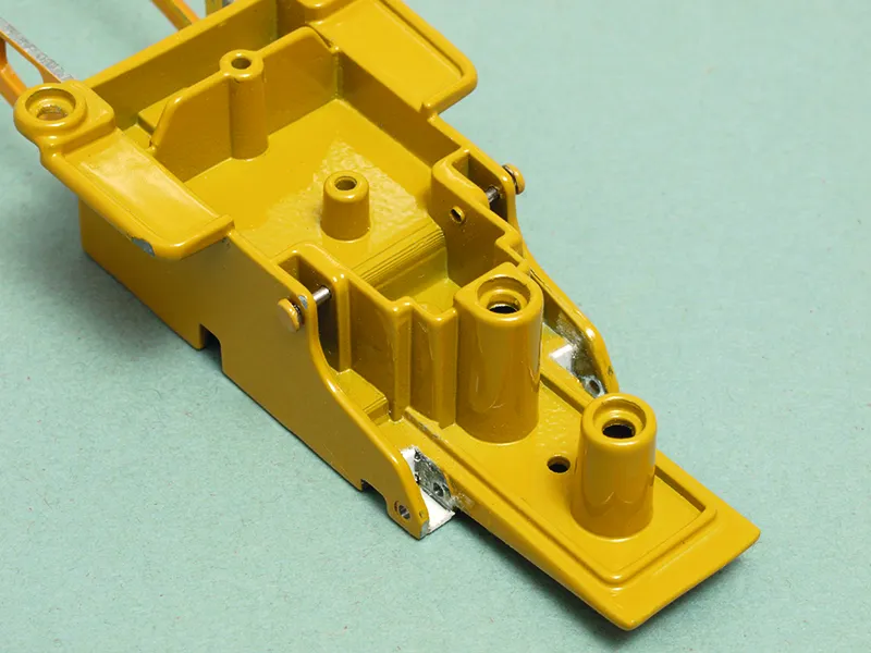
Next, the two rear brackets of the pushing frame on the dozer have to be enlarged to the point at which the lower carrying frame of the front platform from the Welder fits into it according to picture 3.
Picture 3: The altered carrying part with ledge for the front platform.
Unfortunately, the screw holes at the platform and those on the dozer do not match. We use a 1 mm ABS strip to fabricate a ledge for the lower part of the carrying frame for the front platform (picture3). For optical reasons, the four screw holes at the support brackets can be filled with a 3 x 2 piece of tube (? outer x ? inner). The two “half-timber” trusses have to be stripped of all attachments and shortened by a couple of millimetres (see picture 1).
The trusses at the underside of the rear platform now have to be attached in such a way that the two “half-timber” brackets now sit smoothly on their new positions. Both parts of the platforms without their additions can now be joined temporarily. The carrying structure of the front platform can now be placed on the ledge designed for this purpose and the rear part of the platform needs to shimmed until it is horizontal. In this position the two “half-timber” trusses can now be glued to the rear of the dozer (see picture 1).
Before gluing the two platform pieces together, the right opening where the hydraulic lines of the cranes are fed through, should be slightly enlarged. The fire extinguisher mounted at the front left is a detail part from the model trucking sector. The finished platform should now rest on the ledge and “half-timber” trusses completely horizontal according to picture 4.
Picture 4: The four sub-assemblies before test mounting. The platform still needs a trip to the spray booth.
Wordt vervolgd...